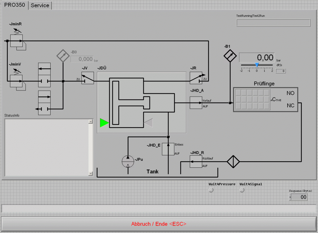
For the hydraulic calibration of pressure switches a hydraulic pressure test unit was developed.
Therefor the pressure controller PRO350 was designed for the adjustment and the final control of precision pressure switches.
Tasks:
A manufacturer of hyraulic precision pressure switches that are used in the field of avionics has to put his specimen through paces as part of his production and final quality control tests. Following requirements had to be fulfilled:
- High-Voltage-Test
- Insulation-Resistance-Test
- Leakage-Test
- Switch-Point-Test
- Bonding-Resistance-Test
Unit concept:
For the hydraulic functional testing the pressure controller PRO350 was chosen and modified with inserts for the above metioned electrical tests.
The pressure controller runs with pneumatic/hydraulic pressure converters and allows a pressure increase up to 350 bar. The test medium is the testing oil © Skydrol that is used in the aviation field and is well known as non-flammable.
The tests are divided in partial tests of the switching contacts of the pressure switch. The electrical tests are performed with a pressure either significantly higher or lower than the expected switching points. If possible, a parallel testing is done.
To record the switching points a pressure ramp for rising and falling pressures is driven. While pressure is rising and falling the micro controller PRO350 is monitoring the state of the switching contacts and corresponding pressure values of in this case 6 specimen. After the functional test for each specimen the switching point, the time of flight and the possible bounce time are defined as result.
All test results are documented and for each specimen a report is generated and printed automatically. All reports are completely generated in XML so they can be opened easily in all browsers or be analyzed with other programs.
The PRO350 realizes the pressure with a pressure converter, this means that a regulated pneumatic pre- pressure (provided by an EPK) is set on a pressure converter which converts it to an adjustable hydraulic secondary pressure. Leaks on secondary side or air inclusions are regulated or oil is refilled until the target pressure is reached again.
The pneumatic unit consists of the pressure supply connection, the pressure reducers for the reset pressure, the control valves and the pneumatic-driven oil pump, the control valves for inlet and outlet and for the reference pessure sensor and further of the reversing valve for moving forward or resetting the piston of the pressure transducer.
The hydraulic unit consists of the pressure transducers, the oil tank, the reference pressure sensor 350 bar, the oil input / output and reversing valve ( with 90µ filter), the overflow valve for pressure limitation and the manometer for the plausibility check. The end positions of the high pressure compressor piston are shown by the end position switch.
Principle of function: Via external control command by the microprocessor the pre-selection of the pressure at the pneumatical unit is set. The pressure is adjusted and pushes the pressure transducer piston forward – as far as the reversing is not active. Now the output pressure is built up as long as both pressures (pneumatic primary pressure and hydraulic secondary pressure) are in balance.
The conversion factor 1:50 allows with the existing pressure supply a pressure increase on secondary side up to 350 bar.
In case of an error the unit switches automatically off. The pressure can be reduced at any time by pressing the button “zero pressure/ emergency switch-off”. The specimen adaptor is covered with a protection hood. The high pressure can only be performed when the cover is closed (contact at the door).
The communication with the external control PC and the integrated programs runs via USB. This offers not only a high data transmission but also options for the measurement of time of flight and of the bounce time can be realized by the performance of the micro controller itself. Above this also a faster, event oriented failure handling was realized. For the test operation is therefor a highest level for the operation safety given.
The pressure test unit PRO350 is accommodated in two 19″ slide-in housings. The electronics and the hydraulic unit, including the oil collection trail, were separated due to the aggressiveness of the ©Skydrol.
The high pressure piping connections are in stainless steel with a diameter of 6.14 mm. The maximum pressure allowed is 350 bar. With the use of NormalOpen valves, in case of a power or pneumatic failure a reliable zero pressure setting is ensured.
Software:
The software was realized with © LabView.

On the user interface an active pneumatic/ hydraulic plan was created. This means that an intervention in the process by the operator – if authorized – is possible at any time.
Active switches, their switch settings (Common, NormalOpen and NormalClose) and the protection cover status are displayed, as well as the relevant parameters and the status messages.
For the switching point detection a given pressure ramp is driven (delta P adjustable in the range of 0.01 to 5 bar/s) and the switch states and pressure readings are measured during this time. Switching points, time of flight and possible bounce times are determined and evaluated.
Test reports are generated in XML format and allow a flexible adaptation to new specimen types and a simple presentation via Brower etc.
Summary:
- Measuring range: 0 to 350 bar relative
- Reference pressure sensor: with characteristic curves linearization, system failure <0,05% full scale
- Medium: (compressed) air / © Skydrol
- Measuring range high voltage: 0 to 1kV
- Measuring range insulation resistance: 10 to 2000 MOhm
- Measuring range weld seam test: 0 to 10mOhm
Don´t hesitate to contact us for further information!