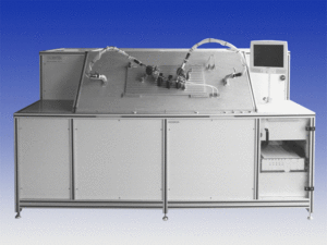
For a further customer we have developed a differential pressure and flow test unit for exhaust pipes (EGR pipe with venturi nozzle) – briefly exhaust pipe flowrate testing unit.
The unit PRO PQ is a testing device during production for EGR pipes. The short is for “exhaust gas recirculation”.
Introduction:
EGR pipes are a very important part in motor vehicles. They are used for the recording of the air volume. A part of the exhaust gas is diverted by the EGR pipe, with the amount of air depending on the operating status of the engine.
With a pressed-in screen a pressure drop is generated. This pressure drop changes in relation to the flow rate “squared”. In front and behind the screen are two measuring points where a differential pressure sensor is connected. As the pressure drop at the screen is proportional to the prevailing flow, the on-board computer of the vehicle can calculate it with the signal of the differential pressure sensor, so that the control functions are triggered for an optimum engine management. Especially with regard to tightened exhaust gas regulations, precise descriptions of the operating conditions of the engine are important.
Task:
For the manufacturer the random monitoring of the EGR pipes (specimen) as part of the developement and quality control is essential. There is a risk of recalls of the delivered vehicles in case of noncompliance with the exhaust emission limits.
From each batch the data of 3-5% of the specimens has to be verified. So the unit concept had to fulfill not only the technical requirements for testing and measurement but also the requirements for an ergonomic working for the operator of the unit.
Further a certain range or specimen properties concerning diameter, screen opening and the shape variety had to be considered. Additionally the specimen has to be tested both for an overpressure- and for an underpressue operating without a change of the flow direction.
Measuring concept:
The test procedure provides the target specifications of differential pressures at the screen. Increasing in a overpressure mode, e.g. +2,5…+400 mbar and decreasing in a vacuum mode, e.g. -2,5…-400 mbar. At the same time the prevailing flow is detected by a high- precision mass flow sensor. With switching units the air flow is thus redirected during the change from the over-pressure mode to the vaccum mode, that the flow directions and also the pressure gradient remain the same via the screen.
For the control of sealings, reproducibility and so on, a reference measurement is performed at regular intervals with a “master” EGR pipe.
During the actual test, the results of the specimen are compared to those of this reference measurement and evaluated as a result (good/ bad statement).
Unit concept:

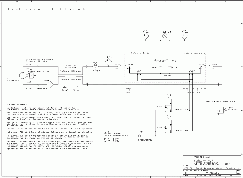
- Pressure generation: For simulating the exhaust gas flow a blower is used. The performance and thus the flow rate and the maximum pressure were designed in such a way that the specified conduction values are achieved for all specimens.
Stepless starting up of the required pressures via operation of the blower engine with frequency converter.
Maximum pressure: +500 mbar over-pressure and -400 mbar vacuum
Maximum flow: > 60 Nm³/h for over- pressure/ vacuum operation - Differential pressure measurement: To display the setpoint for the simulation of the gas mass throughput a high precision differential pressure sensor is used. Test point: directly in front and behind the screen
Measuring range: 0…400 mbar - Mass flow sensor: The mass flow is determined by a sensor that woks accoring to the hot wire principle. The advantage is the very high accuracy and the compensation of air pressure – and temperature conditions.
Measuring range: 0…60kg/h - Absolute pressure measurement: additionally in front and behind the screen ( dynamic pressure)
Measuring range: 0…1600 mbar absolute - Temperature measurement: gas temperature measuring when entering the mass flow sensor (Pt100)
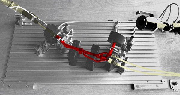
- Adaption of the specimen: To realize an ergonomic working, there are clamping devices for the different specimen types available. These are mounted in the testing unit. The EGR pipe can be mounted only in a defined position – with available clamping devices.
With a two- hand operation the pneumatic clamping device can be closed.

- Adaption of the pipe ends: The pipe ends are connected and sealed with pneumatic controlled quick connection adaptors.
- Adaption of the differential pressure sensors: With slide in adaptors on pipe ends at screen measurement points.
Software:
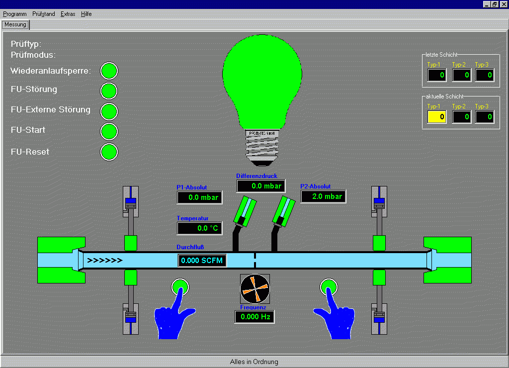
Part of the unit is a PC with the operator software interface and the database administration. The PC is communicating via serial RS232 interface with a micro-controller that provides all operation functions and measurement data acquisisition. The software is also in Englisch available.

In normal operation only the desktop is visible – the operator doesn´t need to intervene via keyboard.
Test procedure – START, STOP or MOUNT and DISMOUNT of the specimen can be executed with the corresponding buttons directly at the test unit.
The collected data is stored in a database and can be prepared with corresponding driver software and access possibilities of other programs. Network connection or access via intranet or internet are also possible.
Summary:
The differential pressure and flow unit for exhaust pipes allows a rational production- accompanied quality assurance. The individual constellation of all test unit components allows a customized modification according to the customer poduction process.
Feel free to contact us for further information!
